Flow Induced Vibration – Diagnosis, Prognosis, Treatment
(By Wade Draper, WKC Group)
Introduction to Quantitative FIV Main Line Analysis
Any structural system will exhibit a series of natural frequencies which depend on the distribution of mass and stiffness throughout the system.
In the case of piping systems, this is influenced by:
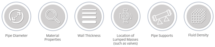
Each natural frequency will have a unique deflection shape associated with it, called the mode shape, which has locations of zero motion (called nodes), and maximum motion (called antinodes). The response of the pipework to an applied excitation is dependent upon the relationship between the frequency of excitation and the natural frequencies of the system, as well as the location of the excitation relative to the nodes and anti-nodes of the respective mode shapes.
A successful FIV assessment, at a high level, results in offsetting the natural frequency and excitation frequency, as well as the location of excitation relative to the nodes and antinodes of the respective mode shapes of the piping system. In effect, the potential for resonance to occur from the interactions between the piping system and the mechanisms of excitation that act on the system (i.e., flowing fluid) will be reduced, enhancing the overall integrity of the system with respect to flow induced vibration. This is primarily accomplished through the quantification of the system’s stiffness relative to the flow through the system and is represented in the form of a scoring mechanism known as the Likelihood of Failure, or LOF for short.
The LOF is a quantitative metric used to score pipework for screening purposes and is not an absolute probability of failure, nor an absolute measure of the fatigue failure, but is rather a conservative measure of operational integrity and is based on simplified empirical models to ensure ease of application.
Flow-induced turbulence exists in most piping systems, with straight pipes generating turbulence primarily through interface with the flowing medium and the pipe wall, known as the turbulent boundary layer. For most practical cases however, the dominant sources of flow-induced turbulence are major flow discontinuities in the system, including process equipment, partially closed valves, short radius or mitred bends, tees or reducers. These major discontinuities lead to the potential for high levels of broadband kinetic energy to develop local to the turbulent source. Some energy resulting from broadband excitation has the potential to match the natural frequency of the piping system and cause resonance.
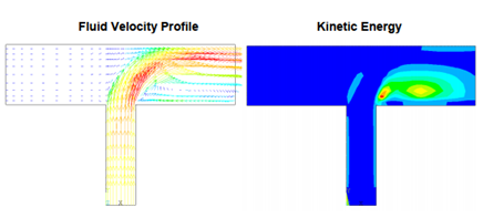
Figure 1 – An Example of the Distribution of Kinetic Energy due to Turbulence Generated by Flow into a Tee
Most of the excitation is concentrated at low frequency (typically below 100 Hz). The lower the frequency, the higher the level of excitation from turbulence. This leads to excitation of the low frequency modes of the pipework, in many cases causing visible motion of the pipe and in some cases, the pipe supports. Vibration generated in the pipework may lead to high cycle fatigue of components (such as small-bore connections) or, in extreme cases, to failure at welds in the main line itself.
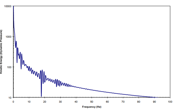
Figure 2 – Turbulent Energy as a Function of Frequency
Scoping / Diagnosis
The scoping process enables the design team to focus on lines with the perceived potential of experiencing high levels of long-term, low frequency, flow induced vibration, and is undertaken on the basis of easily identifiable flow conditions (such as intermittently flowing lines, flow-by-gravity lines, non-process critical lines, etc.), service functions (Fire Water lines, etc.), or any other scoping criteria identified during the assessment (i.e., ρv2 < 5,000 kg/m.s2). It is through the scoping process that we are able to diagnose potential issues of flow induced vibration, before proceeding to screening and detailed assessment.
Screening / Prognosis
The process, prescribed by the Energy Institute (EI) Guidelines involves both the quantification of kinetic energy ‘acting’ on the piping material, as well as the quantification of the pipe ‘stiffness,’ which is primarily governed by an applicable span length criterion as per the EI Guidelines methodology. A summary of the applicable span length criteria and associated typical natural frequency is presented in the following graphic.
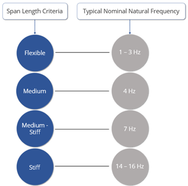
Figure 3 – FIV Span Length Criteria
Any lines assessed at the ‘flexible’ (lowest frequency response) support regime which present a ‘Likelihood of Failure’ (LOF) below 0.3 is deemed low risk, in accordance with the EI Guidelines, with lines presenting an LOF greater than 0.3 being screened further in the detailed assessment phase, in which multiple levels of analysis are used to contextualize the integrity of the line.
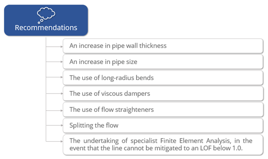
Detailed Assessment / Treatment
In the detailed assessment, all lines of moderate to high risk are optimised with respect to stiffness arrangement. Once span lengths and natural frequencies are optimised to the furthest extent possible through iterations between WKC’s vibration team and our client, recommendations are made in order to further improve the integrity of the system, such as (but not limited to) those listed as follows: